
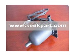


Tank type engine heater
Please refer to specific instruction that accompany heater
Caution: Do not plug the heater into a power source and use it in the air before following steps being finished. Ensure the heater is full of coolant. If the heater is installed by technician, the user must adhere to the following instruction closely.
Installation instruction:
1. Drain and clean the cooling system thoroughly;
2. For the engine with outlet, remove the plug of the outlet, connect the hose to the outlet and apply sealant to screw thread;
Note: For the engine without outlet, connect the lower radiator hose to the inlet of the heater with a clip;
3. See instruction C. Mount the heater to the chassis or other suitable positions vertically and below the lowest portion of the engines water jacket. Ensure the inlet of the heater is below the outlet for engine coolant;
4. Connect the connection point of the engine outlet or the lower radiator connection point to the inlet of heater with a 5/8 inch heater hose which should be as short as possible. Clamp the hose tightly. The connection for outlets has been finished.
5. Connect the heater outlet to the highest accessible point in the engines water jacket area with the hose. (See instruction C). To ensure the normally running, the connection point of the regurgitant hose should not below the highest level of coolant.
If a connection point is available in the engine water jacket, connect the heater hose to the cylinder head as the instruction D. Install the filter with three way pipe as the instruction B. Caution
If the vacuum or manual heater valve is available, the filter with three way pipe should be installed to the other hose in opposite direction as the instruction B.Connect the heater outlet to the engine with a 5/8 inch heater hose (not supplied). Clamp the hose tightly. The hose should be short as possible and placed round not above the engine. The hose path should be lower than the coolant level and clamp the hose tightly. The connection for inlet has been finished.
6. Refill the engine coolant. Start the engine for 10 minutes to get all air out of the system and ensure the circulation normally. Then shut down the engine and let it cool. Check for leaks and check coolant level.
7. Route the cord, keeping away from hot or moving surfaces.
8. Plug the heater into a 3 power source and test for proper operation. The engine block should feel warm to the touch in the area where the heater outlet hose joins the block.
Note: The heater can work when the coolant temperature is below 80 for heater has a thermostat inside.
If the coolant can not cycle, check:
1.whether the heater is mounted too high
2. whether the heater is mounted aslant.
3. whether the cooling system has been polluted.
4. whether the hose looping result in air in
5. whether the vacuum valve has been closed.
6. whether the coolant temperature is higher than 100F.
The operation of heater
For safety and get the best performance of the heater, please refer the operation step by step.
1.Plug the pin in the good contact socket of 110VAC.
2.Use the fresh coolant to cool the cooling system.
Installation instruction (Optional thermostatically controlled.)
The TPS heater in the chart EFG included the optional parts for the control of the coolant temperature.
The standard thermostat in the heater can limit the high temperature. It will active when the temperature rises to 140 F. The optional thermostats are used to control the engine temperature.
The following table shows these thermostats for control.
Active temperature | Inactive temperature | Max. Current/Voltage |
60F | 80F-setpoint | 15amp/120V-10amp/240V |
80F | 100F-setpoint | 15amp/120V-10amp/240V |
100F | 120F-setpoint | 15amp/120V-10amp/240V |
< 20F | Could be adjusted between 90F-130F | 25amp/120V-240V |
Crust of thermostat with screw thread
Its a crust of thermostat with screw thread show in the chart E. The crust can be used together with the standard thermostat. Its mounted in a aluminous sleeve and can be screwed in the engine block to dip in the coolant. There are many type of screw thread for the sleeve. These thermostats should be mounted at the furthest point from the inlet of after heating water.
Two types of connections for tube are show in the chart F and the chart G. These connections are designed for used between the engine and inlet of the heater. The crust show in the chart F is for standard thermostat. The crust show in the chart G is for adjustable thermostat showed in the table. These two types of connections should not be used rigid fixation. The best way is add a tube between the adjustable crust and the heater to avoid vibration. If the distance is long between the adjustable crust and the heater, a supported board nears the crust is needed to fixation the tube. Shut off the power source then remove the cap of crust if the set-point of the thermostat is need to be changed. (The adjustable range is between 90F and 130F. Its showing in a dial indicator.)
Engine Coolant Heater
